Dimensioning
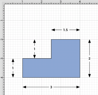
TouchDraw provides variables for determining the dimensions of a selected figure(s) The MinX, MaxX, MinY, MaxY, Length, Width, and Height can be entered as part of the displayed text within a figure. Refer to the available variables table to learn more about what variables can be inserted. These values can be applied to show the dimensions of a drawn object, as shown below:
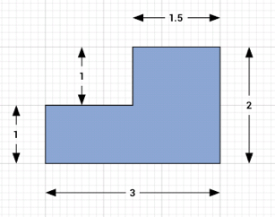
Follow the steps below to create the images shown above:
-
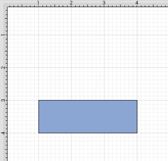
Select the Rectangle Tool and draw a rectangle.
-
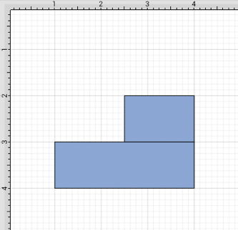
Select the Rectangle Tool again and draw a square on top of the right half of the rectangle. Use the Function Key Feature to select both figures.
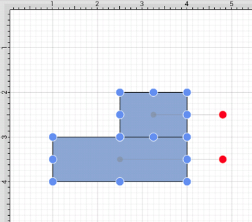
-
Press on the Selection Button to open the SelectionMenu.

-
Press on the Paths Submenu.
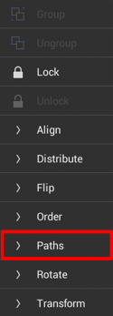
-
Press on the Add Shapes option to combine the two shapes.
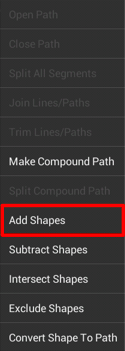
-
The previously blue boundary handles will turn orange to indicate that the two shapes have been combined, as shown below.
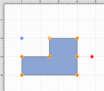
-
Select the Line Tool and create a line with two black arrow end points along the bottom of the rectangle.
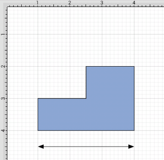
-
Double Tap on the Line figure to open the Text Editor.

-
Enter the variable {DLength} into the Text Editor and then tap on OK in the upper right corner of the editor to dismiss it.

-
The variable will appear on the selected Line after the editor has been dismissed.
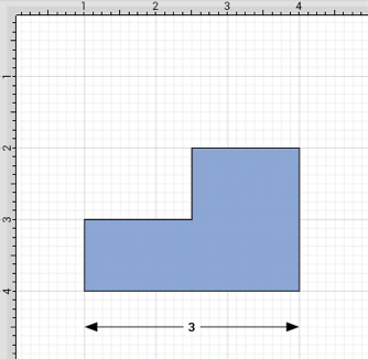
The D and first letter of the entered variable must be capitalized for the value to appear in the selected figure.
-
Follow steps 6 through 8 to create a dimension line for each side of the drawing by entering the corresponding variable in the Text Editor for each side (Width and Height). The figure below shows the completed dimensions for the drawn shape.
