Path Connection Tool
The Path Connection Tool can be used to create a connection between two shapes that can be routed however the user wants using the same tools and flexibility used to modify paths created with the Path Tool.
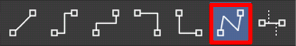
To select the Path Connection Tool, perform an extended Press on the Connection Tool in the Drawing Toolbar.
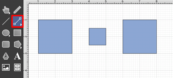
Then tap on the Path Connector Type in the provided selection menu.
This connection between the figures will initially look like a connection created with the Line Connection Tool; however the resulting connection can be modified just as items generated with the Path Tool. See the handling paths section of this documentation to learn more.
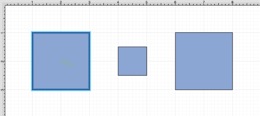
Perform a Touch/Drag gesture combination from the desired starting point on the source figure to a desired end point on target figure and then release the Touch action to complete the connection. The selected figures will be highlighted in blue when a valid connection has been made.
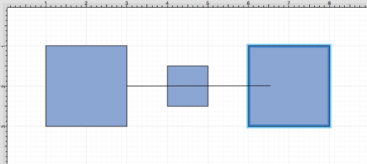
The completed connection will appear as shown below.

Performing a Touch/Drag gesture combination on the second figure after the connection is established results in the connection line position being adapted to keep the two figures connected.
Altering the Route of Path Connection Lines
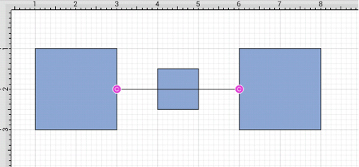
Once the Path Connection Line has been added to the desired target figure from the selected source figure, it can be manuplated in the same manner as a Path Figure. In this example, the connection line currently goes through the middle rectangle.
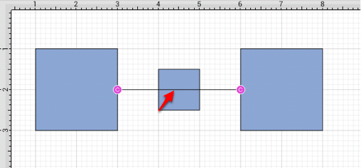
To route the Path Connection Line around another figure, handles must be added to the connection line or it must be converted to a quadratic or cubic segment. These options can be accessed by performing an extended Press on the connection line to open the Contextual Menu or by selecting the connection line and tapping on the Contextual Menu Button in the Top Toolbar.

Several options will appear within the Contextual Menu for modifying the connection line and routing it around a specific figure. Handles and/or curved segments can be added to alter the route of the connection line.
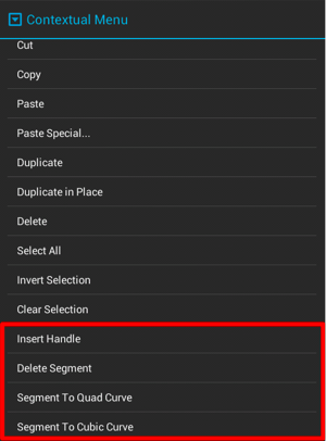
Please note that if you select Delete Segment without adding any additional handles or segments, then the connection line will be completely removed from the drawing.
Example 1: Inserting Handles
Inserting handles and then dragging them to desired points in the Drawing Canvas is one method for altering the route of a Path Connection Line. Follow the steps below to learn how to do so.
-
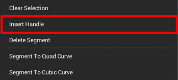
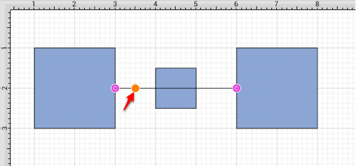
Perform an extended Press on the connection line in a location to the left of the crossed figure and then select Insert Handle from the menu.
-
A new Path Handle (Orange) will appear within the Path Connection Line as shown below:
-
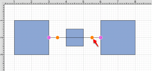
Perform an extended Press on the connection line in a location to the right of the crossed figure and then select Insert Handle from the menu again to add another Path Handle (Orange).
-
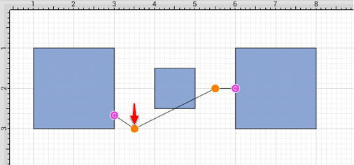
Then press and drag down or up on the left handle to change the direction/path of the connection line.
-
Notice that the line still intersects the figure. Press and drag on the right handle to continue altering the direction/path of the connection line. This will result in the straight segment residing below the figure and a successfully routed Path Connection Line.
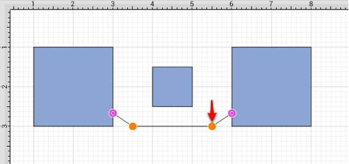
Note: Please note that the handles may be moved in any direction; however, for this example both are moved down to route the connection line around the figure.
Example 2: Segment to Quad
A Path Connection Line can also be routed differently by converting the line to a quadratic segment. This example will use the same original figures as shown previously and will display how to convert the current connection line to a quadratic segment for path routing.

-
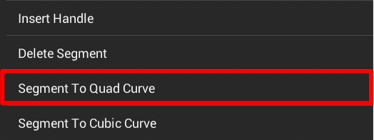
Perform an extended Press on the connection line and then select Segment to Quad from the menu.
-
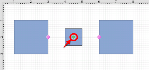
A Control Point Handle (Green) will appear in the middle of the connection line.
-
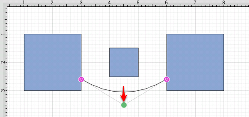
Press and drag the handle downward (or upward) to create a curved segment. The Control Point Handle may be moved in any direction; however, for this example, it is moved downward below the figure.
Example 3: Segment to Cubic
A Path Connection Line can also be routed differently by converting the line to a cubic segment. This example will use the same original figures as shown previously and will display how to convert the current connection line to a quadratic segment for path routing.
-
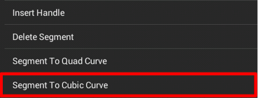
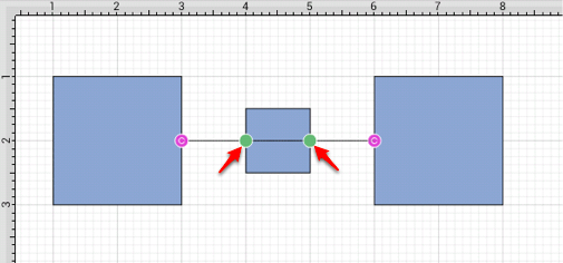
Perform an extended Press on the connection line and then select Segment to Cubic from the menu.
-
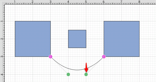
Two Control Point Handles (Green) will appear within the connection line.
-
Press and drag in any direction on the left handle to change the position of the Path Connection Line. In this example, both handles are dragged downward.
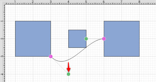
-
Then do the same for the right handle to finish routing the connection line around a figure within a drawing.